|
|
|
The Poor Man’s Solder Reflow Oven A cheap controller and a Walmart toaster oven kept the price down By Tom Burke / May 2012
![]() Photo: Tom Burke Easy baking: A PIC microcontroller is almost all you need to turn a toaster oven into a reflow oven.
Last time I tried soldering small resistors was an experience, I’ll tell you what. They were almost as likely to stick to my soldering iron as they were to stick to the board, and I burned plenty of them in half.
Admittedly, I don’t have the world’s best soldering station. In fact, what I have is a junky old pencil iron, not much better than what you’d buy at RadioShack—no adjustable temperature control and no replaceable tips. I also don’t have US $500 to invest in upgrading my station, but even if I did, it wouldn’t help much. I’m getting older—and so are my eyes.
The solution was obvious: Build a reflow oven!
First off, let’s get all the disclaimers out of the way: This project involves dangerously high voltage at high currents! Be careful!
The plan was a simple one: Design a controller. Put it in a toaster oven. I searched the Internet and found some similar projects. This was comforting, as it meant that the toaster oven would get warm enough to do the job.
I decided to use a PIC microcontroller (from Microchip Technology) and a type K thermocouple as the temperature-sensing device. I did some research on thermocouples. It turns out that I’d need an “ice reference” of some sort. I chose an Analog Devices AD595.
This thing was going to be fully buzzword 3.0 compliant, with three preset control curves (lead/tin, RoHS, and one manual-entry curve), an LCD on the front, and RS-232 communication to monitor the temperature profile from a PC. In other words, I would be able to flow standard lead-tin solder and the “green” solders, and do some custom curves for components that require it (like big, honkin’ FPGAs). I spent some time putting together block diagrams. I even got so far as selecting most of the parts. The total cost would be about $400.
I was just starting to put together schematics when a friend at work ruined the whole project (thanks a lot, Ryan). He pointed me to a company, Annex Depot, that sells PID ramp/soak controllers for about $75. Last time I looked at such things was a couple years back, and they didn’t go for less than about $500. Ain’t Moore’s Law great? Unfortunately, the documentation left something to be desired—it was poorly translated into English from Chinese. Also, the unit that would best fit inside the oven housing was out of stock.
I looked around some more and found another company, Auber Instruments, that sold a similar product (SYL-2352P) that was American-made and had much better documentation, for the same price. Auber also sells the thermocouples (with a 4-inch probe tip), 40-ampere solid state relays (SSRs) for plenty of margin, and SSR heat sinks, all cheaper than I found elsewhere.
Wow! Total cost (including a spare thermocouple and the toaster oven) would be right about $200. I spent $153.85 (including shipping) with Auber and a bit less than $50 at Walmart for a Black & Decker toaster oven with an internal convection fan (to minimize hot spots). It took me less than a day to integrate the system. It took me most of another day to get a reasonable control heating profile (lead-tin) out of it.
Removing the oven’s screws is one of the more interesting parts of this project. The bottommost screw on the back isn’t a Phillips, it’s a “star”—presumably to keep morons like me from cracking the case open and getting electrocuted.
The next trick is the LRF (little rubber feet). These little plugs pull out to access the screws underneath. My oven had a piece of bent metal that scratched my kitchen table. Fortunately, it’s not a new table, and I have kids, so my wife didn’t notice.
![]() Photos: Tom Burke Photos: Tom Burke
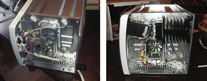
BEFORE AND AFTER: There’s not much to the oven’s innards, so there’s plenty of room for rewiring. Click on image to enlarge.
With the cover off, you can see the innards. There’s not much in there. To the far left, you can see the backs of the controls; in the middle is the fan motor with a cooling fan and protective shroud. See the thermal shield around the black wire? There’s a fusible link in there. I took it out. On the far side of the oven, you can see the metal bars soldered to connect the heater elements in pairs (top and bottom). The long white thing is the door-hinge mechanism—it’s attached to a spring in the back.
It’s easy to pull off the knobs by inserting two standard screwdrivers opposite each other and prying them up. See those metal tabs? Straighten them out as best you can and the metal cover will pop right off the front. You can then remove the controls.
Use the ramp controller as a template to demarcate the area to be cut out—the original opening for the neon lamp was almost perfectly sized for the controller. I used a Dremel tool with cutting disks. (Be sure to wear safety glasses!) Deburr the opening with a steel file.
I used the old control cover as a template for a new control cover, which I made with some 25-millimeter aluminum sheeting from Home Depot. Don’t forget to make tabs to hold it on. (Note: You can bend and straighten those tabs only about three or four times before they break.)
![]() Source: Tom Burke Source: Tom Burke
Click on image to enlarge.
We’re almost there. Drill a hole into the thermal compartment and use two wrenches to install the thermocouple. Bend it into the airflow, just below the shelf.
Connect the wiring to the SSR according to the schematic (above). You need to do this prior to mounting the relay in the chassis because of clearance issues. Note that the fan is wired to run the entire time the system is plugged in. You may also want to add a power switch—it should interrupt power to just the controller and the fan.
The two rear elements are already wired together—just cut their connection to the AC power cord and rewire it to the SSR. Connect the other side of that cut connection to the other side of the SSR; add another wire in that side’s connection to supply the controller. When the SSR is energized, it will supply a path to neutral, allowing the elements to be powered. Connect the two control wires to the SSR, using different colors so you don’t get them confused later.
Mount the SSR on the heat sink, using the supplied sink grease and screws, and drill some holes in the back cover to mount it with machine screws. I would have mounted the sink to the floor of the oven, but that was where the power line came in. Be careful of the fan shroud—there’s just enough room to install the SSR.
Use some heavy gauge wire and wire nuts to connect the top- and bottom-forward heater elements together. Wire them to the remaining AC wire that you cut loose earlier—string off another wire to supply the controller. Pull the controller wiring through the mounting bezel (but not the thermocouple wires), and connect them to the controller outside the unit. Slide the controller into the chassis, pulling the connecting wires up and out of the way of the fan. Install the thermocouple wires on the controller—blue on pin 5, red on pin 4. Install the mounting bezel. Finish wiring the guts, if necessary.
Reinstall the cover. (Make sure you correctly reinstall all the screws and feet.) After a short self-test, the controller should come up as described in the instruction manual. If you did everything correctly, no breakers will trip and no sparks or smoke will come flying out. You can follow the controller instructions to set a steady-state temperature and then test the control. If it works, you’re done!
Corrected on 13 April 2012 to read “When the SSR is energized, it will supply a path to neutral [not ground] allowing the elements to be powered.”
About the Author Tom Burke is a Senior Systems Engineer at Oceaneering. He’s originally from a small town in the Midwest, but still managed to earn a BSEE, MSEE, and an MS in Systems Engineering from Johns Hopkins University. He now lives in Pasadena, Md.
|
|


 雷达卡
雷达卡
 发表于 2012-10-6 11:42:19


 QQ好友和群
 QQ空间
QQ空间 腾讯微博
腾讯微博 腾讯朋友
腾讯朋友 微信
微信 收藏
收藏 分享
分享 支持
支持 反对
反对 提升卡
提升卡 置顶卡
置顶卡 沉默卡
沉默卡 喧嚣卡
喧嚣卡 变色卡
变色卡 抢沙发
抢沙发 千斤顶
千斤顶 显身卡
显身卡 发表于 2015-10-26 21:39:46